Contents
Redundancy
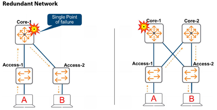
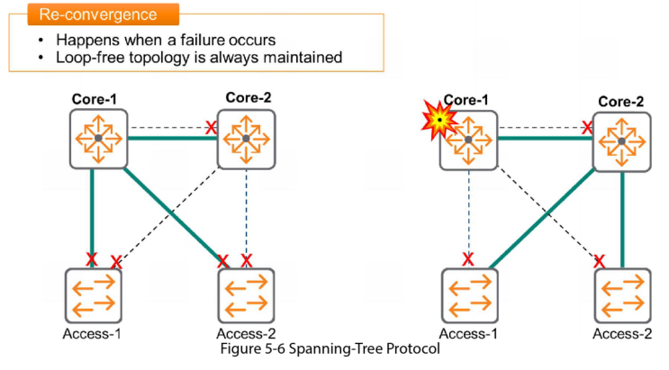
In the above example on the left, if Core 1 fails then the network is down and client A won’t be able to communicate with client B.
In the example on the right, if Core 1 fails the network will say up as Core 2 is available and the Client can communicate through this.
While this mitigates a single point of failure issue it creates a new challenge – Loops.
Layer 2 Loops
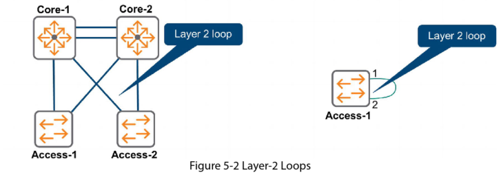
Redundant links create L2 loops which can cause major problems.
Broadcast Storms
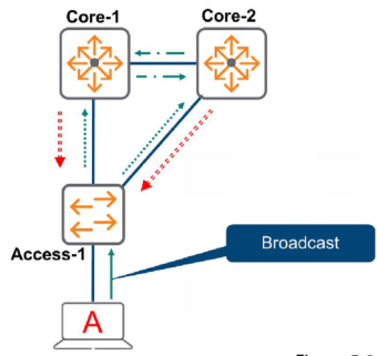
- Switches flood broadcasts out all interfaces in the same VLAN except the ingress port. In this example A sends a broadcast frame
- Switch Access 1 receives this and floods it out (Copy 1)
- Core 1 and Core 2 receive it and flood it out their connections to each other (Copy 2)
- Core 1, Core 2 and Access 1 receive the second copy and flood them out their ports (Copy 3)
- Access 1 receives the 3rd copy and the cycle continues
- Soon all available bandwidth and CPU cycles are used up processing broadcasts. No resources are available to process normal data communication and the network is effectively unusable.
Multiple Frame Copies
If the switch receives a unicast packet to some destination MAC and that address has not yet been learned in the MAC address table, then the switch floods the frame out all ports in the VLAN except the ingress port. These can also circulate and waste bandwidth and CPU cycles, plus cause tother issues.
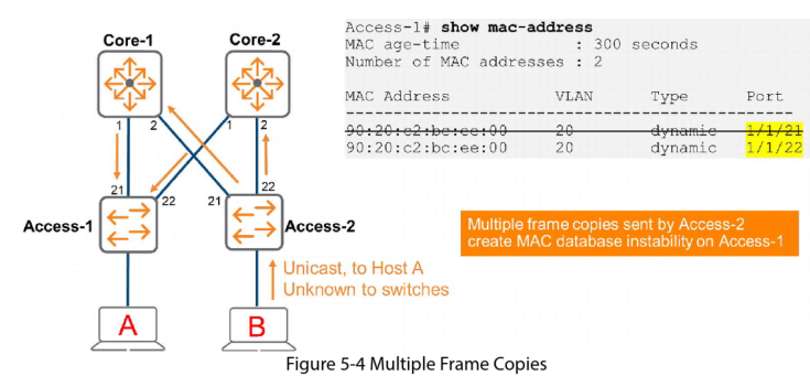
- Host B sends a frame to Host A
- Access 2 has not yet learned Host A’s MAC address so it floods this frame out ports 21 and 22. Core 1 and Core both receive a frame with source MAC 90:………..:00 inbound on port 2
- Both Cores send a copy to Access 1 switch. This switch now believes it can reach Host B via ports 21 and 22. Access 1 is confused, Host B can only exist in one place but it appears in 2 places
- The multiple frame copies generated by Access 2 create MAC database instability on Access 1
Spanning-Tree Protocol (STP)
The IEEE 802.1d standard version of STP was developed to build and maintain redundant, yet loop free networks. STP creates a loop free topology by automatically disabling redundant links. However, these links disabled links remain available to provide redundancy in the case of a failure.
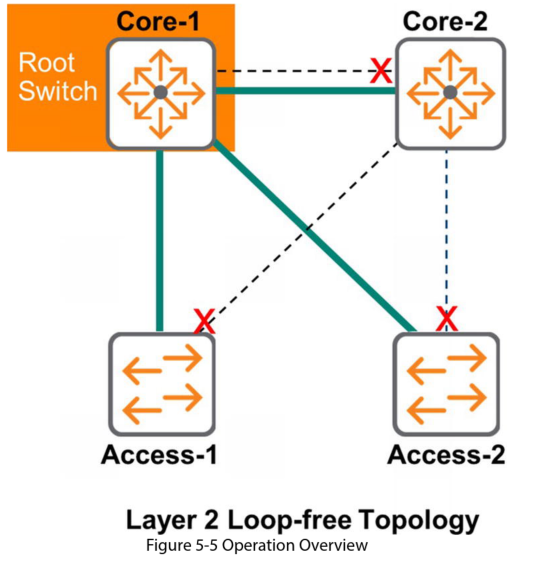
One switch in the Spanning Tree domain is elected as the bridge or Root switch. The root bridge is the reference from which the spanning Tree grows. All other switches are non-root bridges, sometimes known as designated switches.
When discussing STP the terms switch and bridge are used to describe the same thing
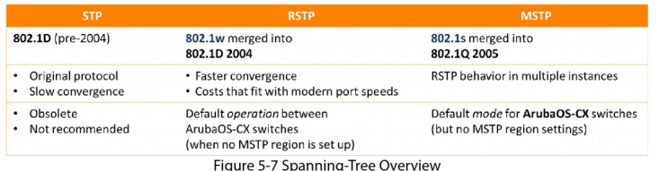
In the original standard only the root switch sent hello packets every 2 seconds. These were forwarded on to the rest of the switches in the domain. If a switch didn’t receive a hello packet for 20 seconds (the default MAX age timer) an outage was assumed and the switches converged to a new topology.
Rapid Spanning-Tree Protocol (RSTP) was developed in 1998 to speed up convergence. In RSTP all switches send Hello packets. The need for Max Age timers is eliminated.
RSTP elements
Bridge Identifier
Spanning Tree assigns each switch a unique identifier called a Bridge ID. This is composed of a 2-byte priority and 6-byte MAC address. The default priority is 32768. By default each switch has the same priority, but each switch has a unique MAC address so the Bridge ID is unique.
Bridge Protocol Data Units
All switches in the Spanning Tree domain exchange control messages called Bridge Protocol Data Units (BPDUs). In the original STP only the root switch sent them.
In RSTP all switches send BPDU’s with their current information every 2 seconds, the default hello time period. If a port doesn’t receive BPDUs for three consecutive hello timers, the switch quickly knows it has lost connectivity to the neighbour and begins to converge. Because each switch sends BPDUs it is a truly keepalive mechanism. Failure detection takes no longer than 6 seconds.
Port States
During Spanning Tree establishment, and any ensuing convergence, switches must decide which ports will forward data and which ports must be disabled to prevent L2 loops.
The table below lists the states were used in the original STP (802.1d) and the RSTP (802.1w) and compares them
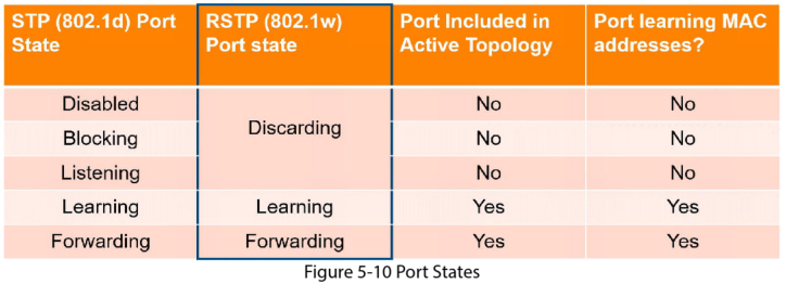
In RSTP the Leaning state is a transition state and is only used during re-convergence of the protocol when change happens. Stable states are the Discarding or Forwarding states.
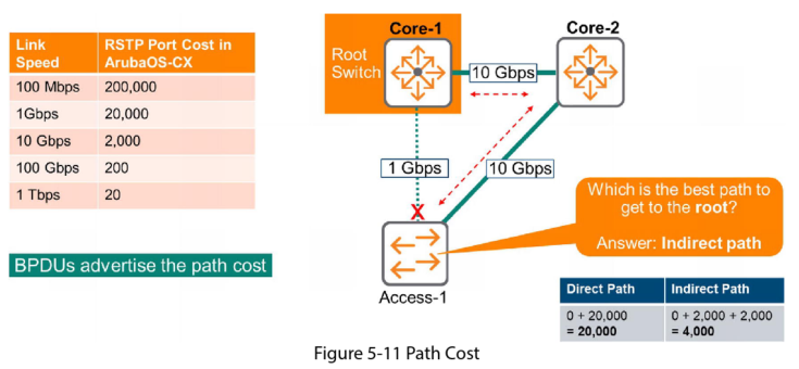
Path Cost
RSTP may have several possible paths to get from route switch to a particular non-root switch. It chooses the best path based on coast, which is based on link speed.
Port Roles
Designated Port:
- This is a port facing away from the root switch
- Ports on root switch and designated switches. All ports on root are designated
- Port state = forwarding
Root Port:
- These ports lead towards the root
- Ports on non root switches with the best cost path to the root bridge. These ports forward data to the root bridge.
- Port state = forwarding
Alternate port:
- All ports left that are not Root Port or Designated Port
- No loop to itself
- Becomes the root port if the active fails
- Port state = Discarding
Backup port:
- Not the closest to the root switch
- Creates a loop to itself
- Becomes the designated port if the active fails
- Port state = Discarding
RSTP Operation
Operational Overview
RSTP algorithm creates a loop free network by the following steps:
- Elects Root switch
- Select root port on all non-root switches
- Select the designated port on each switch to switch link
All other ports move to a blocking state to prevent loops
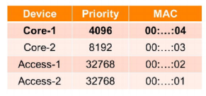
- Root Switch Election
This is based on the Bridge ID (BID) which is made up of a priority number (default is 32,768 but you can set it yourself) and the switch MAC address. The switch with the lowest BID wins.
The priority must be configured in increments of 4096. In the example table below you can see Core 1 has the value of 4096 and Core 2 8192
- Select root port on all non-root switches
Non root switches must select the best path to the root switch by selecting its root port. Root port criteria are as follows:
- Lowest root Bridge ID
- Lowest path cost to the root bridge
- Lowest sender Bridge ID
- Lowest port priority
- Lowest port ID
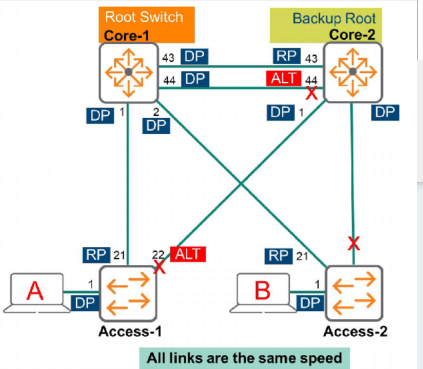
In the diagram above, Core-2 receives BPDUs on ports 1,2,43 and 44. Core 2 must decide which port is the Root port.
- Lowest root Bridge ID: all devices agree that Core 1 is the Root switch. This does not help to select the best path
- Lowest path cost to the root bridge: All links are the same speed, then the indirect paths (ports 1 and 2) are discarded because the cost is higher. Ports 43 and 44 have the same cost so it is a tie.
- Lowest sender Bridge ID: BPDUs received on ports 43 and 44 are send by the same device. This criteria does not help to break the tie.
- Lowest port priority: the sender will include a port priority in the BPDU. The port priority comes in the range between 0 and 240 (the lower meaning the higher priority). The default is 128. If the defaults are being used the priority is the same and therefore does not help to break the tie.
- Lowest port ID: the lowest port id is the winner. Which in this case is port 43. Port 43 becomes the Root port.
- Select root port on all non-root switches
The criteria to select a Designated port is the same as the Root port.
- Lowest root Bridge ID
- Lowest path cost to the root bridge
- Lowest sender Bridge ID
- Lowest port priority
- Lowest port ID
Edge Ports
Edge Ports connect to endpoints and do not receive BPDUs. This means they don’t need to be part of the Spanning Tree algorithm and can therefore quickly transition to the forwarding state with no intermediate steps. If BPDUs are received on an edge port, then the port will act as a normal Spanning Tree port and participate in the algorithm. You must manually configure Edge ports.
Switch(config)#interface 1/1/1
Switch(config-if)# spanning-tree port-type admin-edge
An alternative to the admin-edge option is the AOS-CX administrative-network option. With this option the port looks for BPDUs for the first 3 seconds after the link is up, if non are received the port becomes an edge port and immediately forwards frames. If BPDUs are detected it becomes non-edge port and participates in normal STP operation.
Switch(config)#interface 1/1/1
Switch(config-if)# spanning-tree port-type admin-network
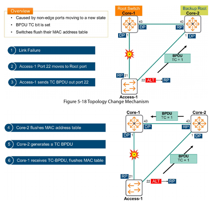
Topology Change Mechanism
In RSTP a topology change occurs when non-edge port move to a different state or BPDUs are no longer received.
Topology change process:
- A switch detects the topology change
- This switch informs the rest of the switches in the network by setting the TC (Topology Change) bit in the BPDU and transmitting these BPDUs
- The switch flushes its MAC address table entries associated with all non-edge ports
- Other switches receive the BPDUs with the TC bit set, they then clear the MAC address table entries on al ports except for the one that received the BPDU
- These other switches then send BPDUs with the TC set