Contents
Link Aggregation
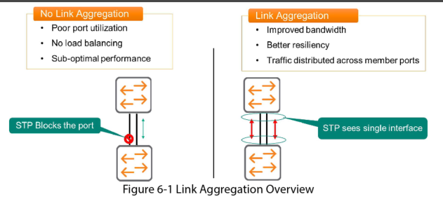
Without link aggregation, if you used two links to connect two switches together, the two links would create a loop and STP would automatically block one of the ports.
Link Aggregation fixes this issue by bundling multiple physical interfaces into a single logical interface. Since STP sees this as a single interface there is no blocking.
Advantages of Link Aggregation
- More bandwidth because traffic is spread across multiple ports
- Better resiliency because if one member fails the remaining links carry the load
- Convergence is faster than STP because there is no need for an STP Topology Change notification
When you enable Link Aggregation on a switch the protocol creates a virtual interface. You then configure physical ports to be members of that virtual interface. In AOS-CX this is referred to as a LAG (Link Aggregation group).
NOTE: broadcast and multicast traffic sent across only physical link in the bundle. This ensures that Link Aggregation dose not create a Layer-2 Loop.
Link Aggregation Requirements
Interfaces that are mapped to the same LAG must be configures in a consistent manner. The following items must match:
- Duplex mode
- Link speed
- Media
Each LAG can have up to 8 individual ports
Static and Dynamic LAG
Static LAG
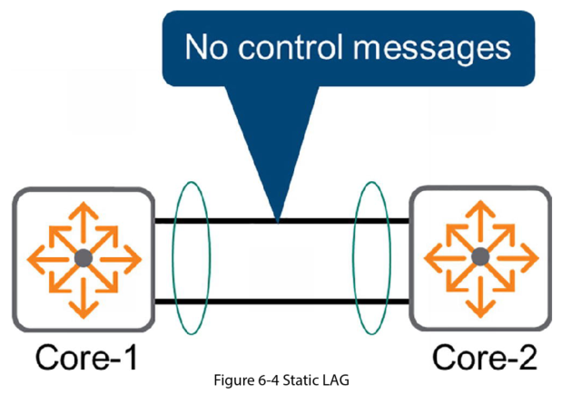
In a static LAG devices do not exchange any control information. You configure the LAG independently on each peer. If the configuration is good, it works. However the switch peers have no knowledge of who they are connected to.
This mode is not recommended because a misconfiguration on one side is not detected by the peer. This can lead to unexpected behaviour which is hard to troubleshoot.
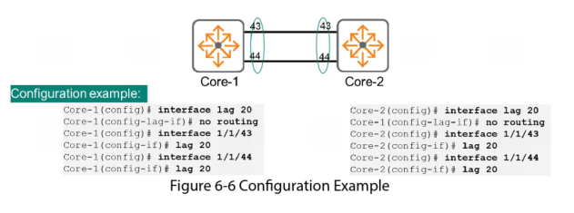
Configuring Layer-2 Static LAG
Create a LAG interface with an identifier between 1 and 256
Interface LAG 1
Disable routing (Layer 3 capabilities). This step limits the LAG to only process Layer-2 frame headers
No routing
Map a port member to the LAG
Interface 1/1/1
LAG 1
Dynamic LAG or LACP
Devices that use Dynamic LAG exchange control messages to establish and maintain the LAG. This will detect link failures and ensure that LAG port members terminate on the same device.
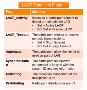
The standard used to implement this is Link Aggregation Control Protocol. LACP exchanges periodic messages called LACP Data Units. These messages include:
- System ID: this uniquely identifies the switch
- Operational key: this uniquely identifies the LAG
Some other information in the LACP Data Units:
Dynamic LAG or LACP is the recommended way to implement Link Aggregation to avoid unexpected network problems.
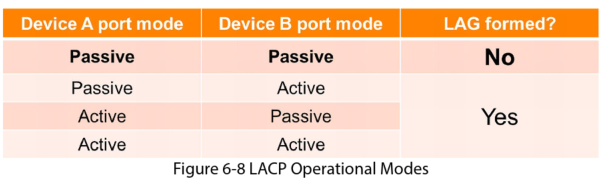
LACP Operation Modes
Passive Mode
In this mode the device passively waits to receive LACP data unit messages from the peer, to dynamically create the LAG. The LAG is in a listening state waiting to hear from its peer. But if its peer is set in passive mode it is thinking the same thing so a functional LAG is never formed. At least one peer must be in Active mode
Active Mode
In this mode the device actively transmits LACP Data Units over its member ports saying “Hey lets form a LAG”. Whether the peer is in Passive or Active mode it responds, negotiation continues, and the AG is successfully formed.
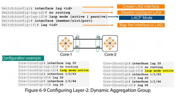
Configuring Layer-2 Dynamic LAG
The config is the same for a static LAG except for one extra line where you specify the LACP mode
Load Sharing
Load Balancing Algorithm
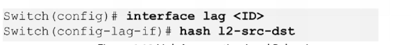
Peer LAG devices use a hash algorithm to balance the traffic load across multiple physical interfaces. A hash algorithm is a one way mathematical function (if you have the output, there is no way to derive the input).
The switches use packet header information as hash function inputs. Depending on the switch this could be:
- Layer 4 TCP/UDP ports
- Layer 3 Source and Destination IP addresses
- Layer 2 Source and destination MAC addresses
In AOS-CX the default input information for the hash algorithm are the Layer 3 Source and Destination IP addresses
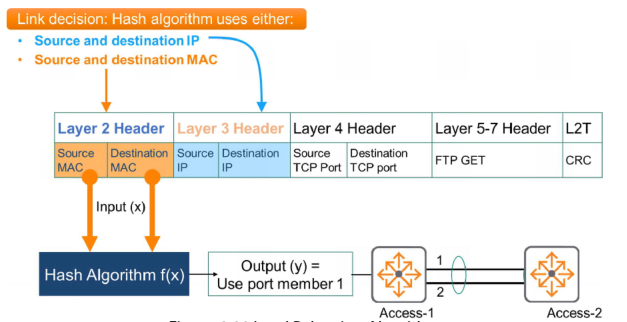
In this example the MAC source and destination addresses are used as inputs for the algorithm. The output is to use port1 for all packets with this source and destination MAC address combination. Only a link failure will cause port 2 to be used for these packet
Link Aggregation Load Balancing
In AOS-CX the default input information for the hash algorithm are the Layer 3 Source and Destination IP addresses. You can verify this by using the show LACP aggregates command. In the example below you can see the highlighted hash information:
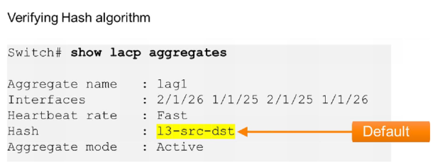
This means it uses Layer 3 Source and Destination IP addresses.
You can change the input it uses for the algorithm. In the following example we change it to the Layer 2 inputs: