Contents
Routing
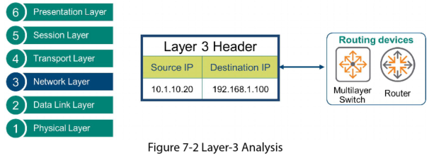
IP routing connects VLANs together and routes packets between them. Routing devices use Layer 3 packet analysis to forward L3 packets.
Layer 2 switches forward frames among devices in the same LAN by processing Layer 2 headers. This is based on destination MAC addresses.
Layer 3 devices move packets between LANs based on Layer 3 IP addresses.
Routing Layer 3 Analysis
L3 devices:
- Analyse L3 IP addresses
- Select the best path to get from source to destination
- Forward the packets along that path
IPv4 Addresses
An IP address consists of 2 parts:
- Network ID – this is the eft side of the address that identifies the network
- Host Id – the right side of the address that identifies the host
An IPv4 address is 32 bits. Some of the bits represent the network ID, some represent the host
When sending packets:
- If the network ID for the source and destination re the same, then both devices are in the same network. L2 switching is enough to complete the communication
- If the network for the source and destination are different, then the devices are in different networks. L3 routing is required for the communication
Network Mask
This indicates how many bits represent the network portion of an address. The remainder bits represent the host portion of the address.
A network mask is 32 bits long. It is a string or block of binary ones, followed by a block zeroes.
- The ones represent the portion of the IPv4 address that is assigned to the network ID
- The zeroes represent the portion of the address assigned to the host ID
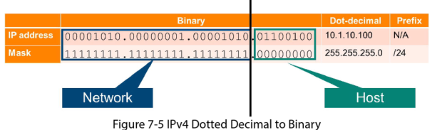
The network mask is usually represented in 2 different ways:
- Dotted Decimal Notation: same as an IP address it uses four different octets and each is separated by a dot. EG: 255.25.255.0
- Prefix notation: this indicates in decimal the number of bits that are set to one. EG: 10.1.10.100/24, this indicates that the first 24 bits are set to one
IP Routes and Default Gateway
IP Routes
When a device wants to communicate with a device in a different network, it must know which local network device on its broadcast domain can route the traffic toward the destination network. This information is provided using IP routes.
On routers and multi-layer switches there are 2 ways to add routes:
- Static: routes are manually added
- Dynamic: this uses a routing protocol to determine the best route
A Static route must have the following information:
- Destination IP address
- Subnet mask: how the destination IP address is split into a network portion and host portion
- Next hop IP address: the IP address of the router on your network that can route packets to the destination
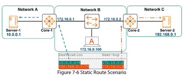
If the above example, if host A (in Network B) wants to communicate with server 1, it looks at the IP routes and sees that the router 172.16.0.1 can get it there.
Default Gateway
A default gateway is a router that connects your host to remote network segments. It’s the exit point for all the packets in your network that have destinations outside your network.
NOTE: different endpoints in the same subnet could have different default gateways if there is more than one router on the network.
Inter VLAN Routing
Multi Layer Interface Types
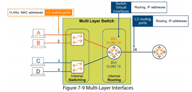
In this diagram ports 1-4 are being used as L2 interfaces. They attach to end systems, accept L2 frames as being part of an L2 VLAN, and forward them based on their destination L2 MAC addresses. In Aruba OS-CX ports are L3 interfaces by default, so you must run the command “no routing” to configure ports 1-4 as L2.
Switch Virtual Interfaces (SVI)
The Aruba OS-CX are multi layer switches; they have both L2 switching functions and L3 routing capabilities. You need a way to connect the L2 VLAN to the internal routing function. To do this
You must create Switch Virtual Interfaces (SVI). The is a virtual L3 routed interface that exists only inside the device as a virtual construct.
In this example you would create SVI 10. As it is an SVI it connects to the internal routing construct. Because it is SVI 10 it connects to VLAN 10 and so services routable traffic from VLAN 10 to other destinations networks.
Scenario: you want to connect this switch to an external router using port 24
Since all ports are L3 by default, port 24 connects to the internal routing function by default. To connect it to the external router you just need to configure the port with L3 parameters such as an IP address.
The SVI’s are virtual L3 interfaces for internal routing, port 24 is a physical layer 3 interface for external routing. Both are L3 and perform routing functions. They accept L3 packets and forward them based on their destination IP address.
DHCP Helper Address
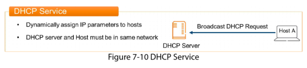
To get a DHCP assigned address, a host broadcasts a DHCP request saying “I need an IP address, a subnet mask and a default gateway”. Because it is a broadcast, the host and DHCP server must be on the same subnet for the host to get a DHCP assignment. The router defines the edge of the broadcast domain and does not forward broadcasts. So if the DHCP server is in another subnet it will not hear this request. In this scenario you would need a DHCP server for every subnet, which isn’t practical.
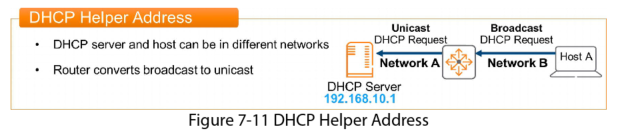
The solution is to configure a DHCP Helper address on each router interface that servers as the Default Gateway for endpoints.
DHCP Helper Address process:
- The client broadcasts a normal DHCP query
- The router (the clients Default Gateway) receives this broadcasted DHCP query
- Instead of discarding the broadcast, as is normal, the router “helps” the broadcast by forwarding it on to the DHCP Server. It converts the broadcast to a unicast, with the destination address specified in the IP Helper-address command (192.168.10.1 in this example). As it is a unicast the router forwards it as it would any other unicast packet towards its destination, the DHCP server
- The DHCP Server receives the DHCP request and replies with a DHCP offer, a unicast message sent to the requesting host, via the router.
In AOS-CX the command IP Helper-Address defines the address of a remote DHCP server. Up to 8 can be defined. When more than one DHCP server has been defined the switch will send the client request to all defined servers
Inter-VLAN Routing
Devices in different VLANs cannot communicate unless you connect them with a router. Inter-VLAN routing connects separate VLANs into a routed internetwork of communicating devices. In the past, multi layer switches did not exist. Older environments used L2 switches for host connectivity, and then routed between them with an external router.
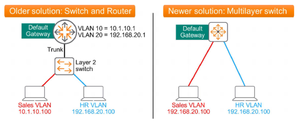
A potential problem with the older solution is that the switch to router links can become oversubscribed. Performance can also be suboptimal because sending frames to the router requires an additional routing decision.
Multi-layer switches are more efficient. The switching and routing functions of the device are connected internally via a high speed backplane. Initial routing decisions happen in the box. This can reduce latency and increase performance.
All AOS-CX switches are multilayer switches and have routing enabled by default.
NOTE: you learn that collapsing L2 services and L3 services into a single multilayer switch can improve efficiency, however, for larger networks there is typically a separate layer for pure L2 switches for endpoint access, connected to a smaller set of L2/L3 multilayer switches. This design improves scalability.
IP Routing Table
Routing devices build and maintain a routing table that informs them of the best path to any given destination. Routes can be added manually or they can be configured using a routing protocol which automatically builds and maintains this table. Typically entries in the table do not expire unless there is a topology change. This differs from the MAC address tables in L2 devices where an entry expires after 5 minutes if the switch stops receiving traffic from the endpoint.
Analysing the route table:
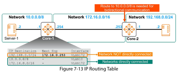
– Entry 1: To get to any host on network 192.168.0.0/24, send packets to next hop router 172.16.0.253
– Entry 2: to get to any host on network 10.0.0.0/8, I am directly connected to that network, simply forward the packets out local VLAN10 interface.
– Entry 3: To get to any host on network 172.16.0.0/16, I am directly connected to that network, simply forward the packets out local VLAN172 interface.
Packet Delivery Scenario
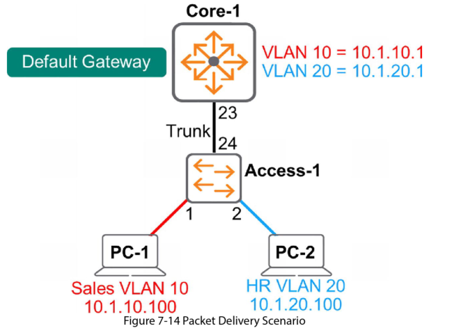
In this scenario PC-1 wants to communicate with PC-2:
1. PC-1 generates a message that has the following info:
– L3 header: source IP: 10.1.10.100 and the destination IP 10.1.20.100
– L2 header: source MAC is PC-1’s MAC and the destination MAC is the default gateway MAC
2. Access-1 switch receives the frame and analyses the MAC address. It finds a match in its MAC address table and knows it must forward this frame out its trunk link, port 24 to Core-1. it adds an 802.1q tag, VLAN=10 and forwards the frame.
3. Multilayer switch Core-1 is the L2 destination of this frame. It accepts the frame, strips off the L2 header and begins to perform its routing function, to analyse L3 header information.
4. It compares the L3 destination IP to its routing table entries. It knows that the destination network 10.1.20.0/24 is directly connected on its Switch Virtual Interface (SVI) VLAN20. Core-1 knows it must forward the packets out its VLAN20 interface.
5. Core-1 builds a new frame to wrap around the IP packet. This frame includes an 802.q Tag, VLAN=20. This frame is sent to L2 switch Access-1.
6. Acccess-1 receives the frame and learns from the tag that it is for VLAN 20. the 802.q tag is then removed. Access-1 compares the destination MAC against its MAC address table, finds a match, so forwards it out port 2 towards PC-2.
Virtual Routing and Forwarding
We have learned you can create several VLANs on a single physical switch. It is as if you have created multiple virtual switches indies the physical switch, one for each VLAN. Similarly, you can create several virtual routes inside a single physical router with Virtual Routing and Forwarding (VRF). VRFs are useful in situations where the IP addressing overlaps in different parts of the network. This could happen when 2 companies merge for example.

This example shows a single multilayer switch split into two separate VRFs.
– Interfaces 1 & 2 participate in VRF 1
– Interfaces 3 & 4 participate in VRF 2
These 2 VRFs do not interact, it as if they are on separate physical routers with no connectivity between them. Therefore, the addressing can be the same in both VRFs without conflict.
The VRFs do not interact by default, but you can configure it to route between the two VRFs if needed.
In AOS-CX, all interfaces (enabled with routing) by default are mapped to the Global VRF called “default”. In other words all interfaces are part of the same VRF. The physical router and the Global VRF are essentially the same thing. AOS-CX also includes a specific VRGF for management purposes and that can only be used in the Out-of-Band Management (OOBM) port, to separate data and control plane from the management plane.